Hebei Zhengtian Fan Manufacturing Co., Ltd.


Contact Us
E-mail:
youtian@hbztfj.com
WhatsApp:
Add:
Renqiu City, Cangzhou City, Hebei province, discuss Bao township Shoulian village east Yi road east

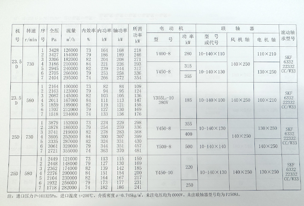
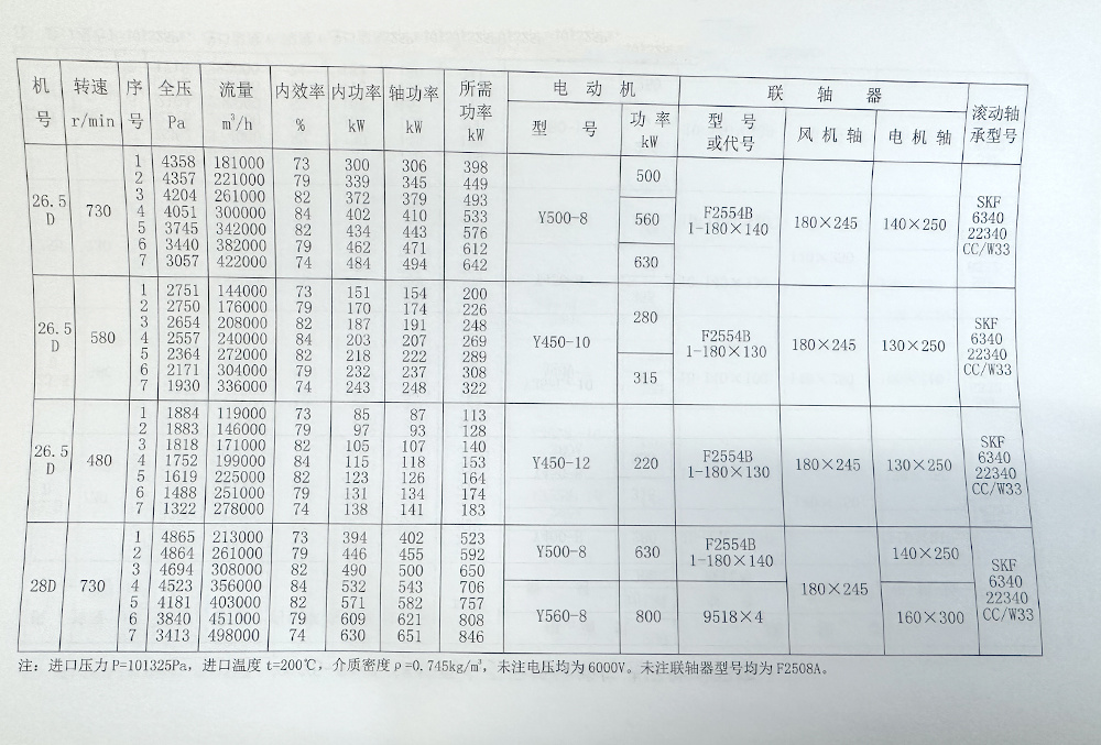
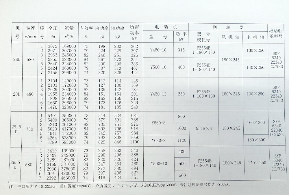
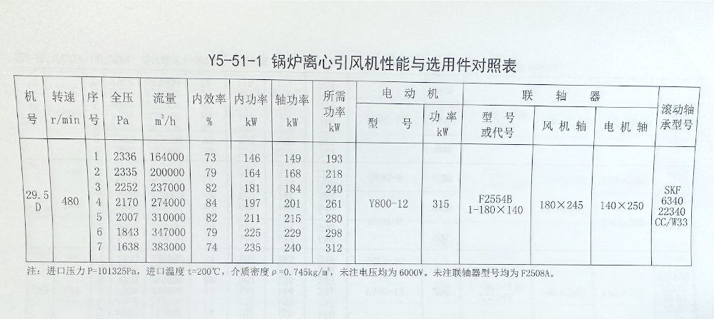
Boiler centrifugal induced draft fan
keyword:


- Description
-
Purpose
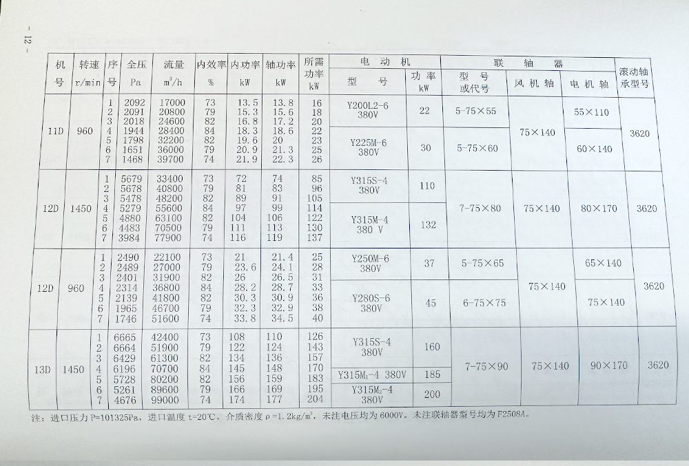
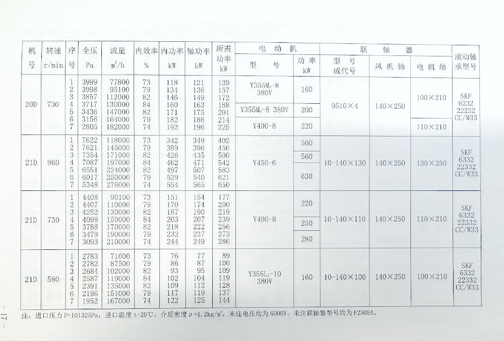
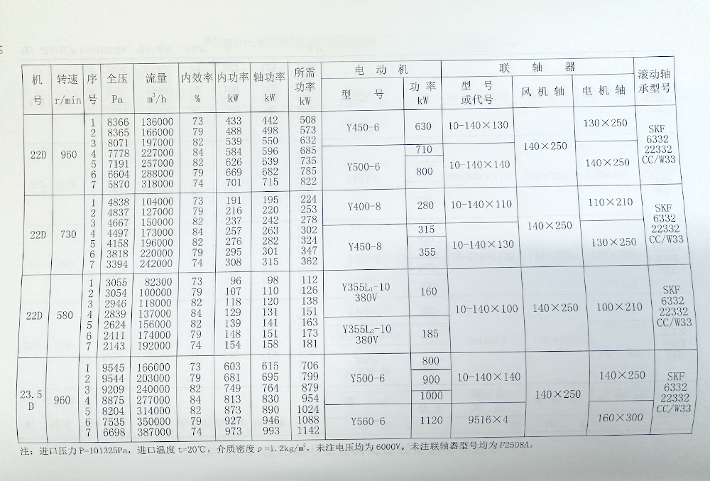
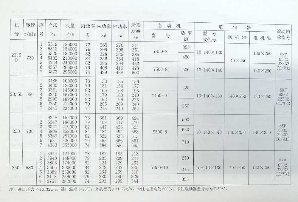
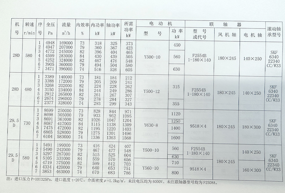
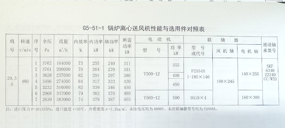
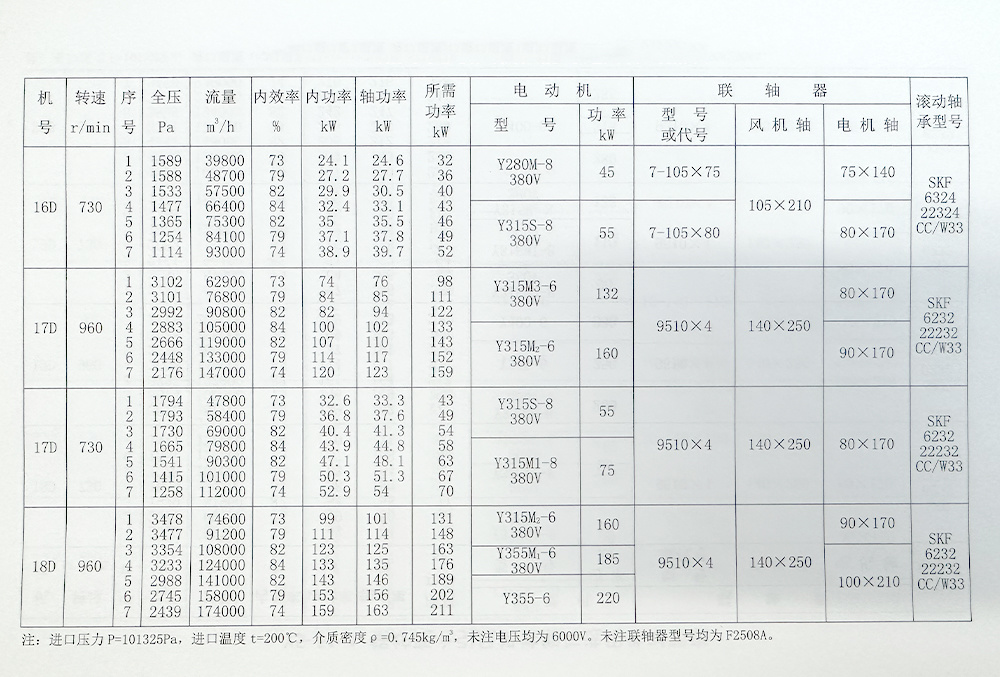
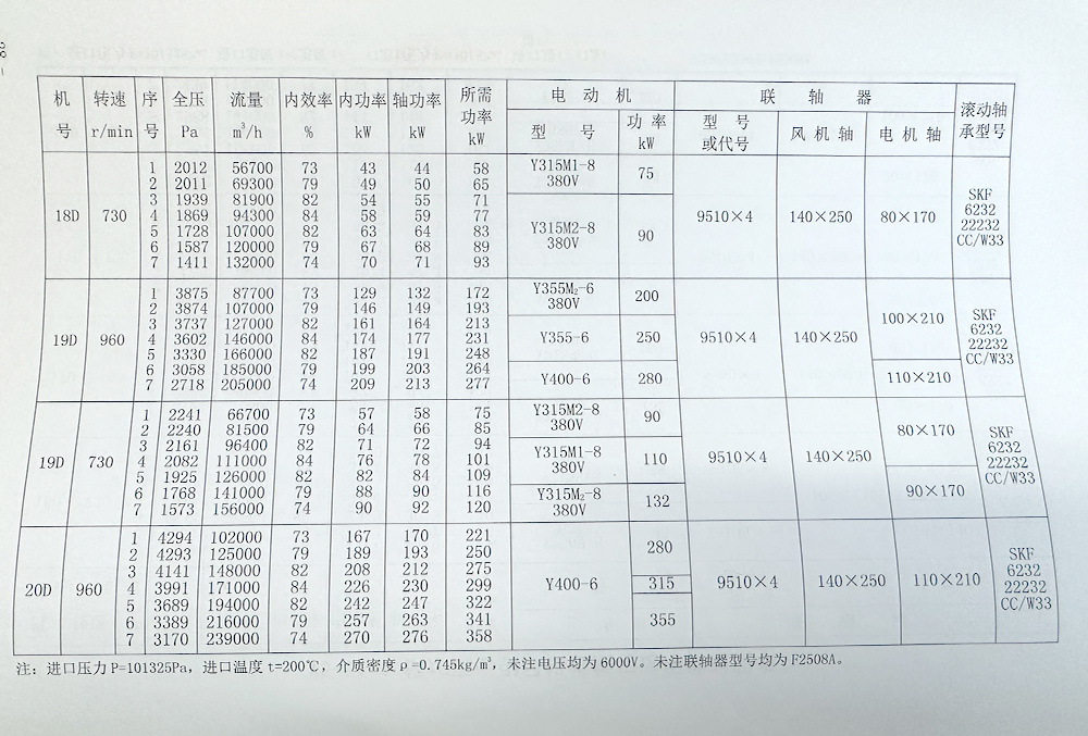
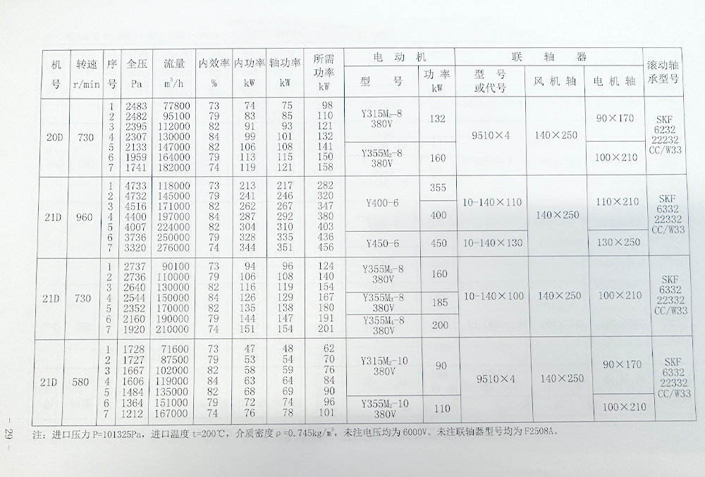
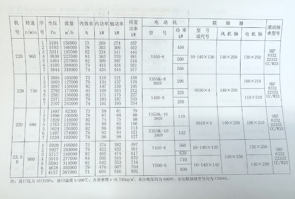
The G Y5-51 type boiler induced draft fan is suitable for the induced draft fan system of steam boilers ranging from 2t/h to 670t/h in thermal power plants. It can also meet the performance parameters required for high-pressure fluidized bed boilers. This series of fans can also be used for dust removal, mine ventilation, and general ventilation systems. This model can be designed as explosion-proof fans, anti-corrosion fans, and high-temperature fans according to user requirements, with the same dimensions as the original model.
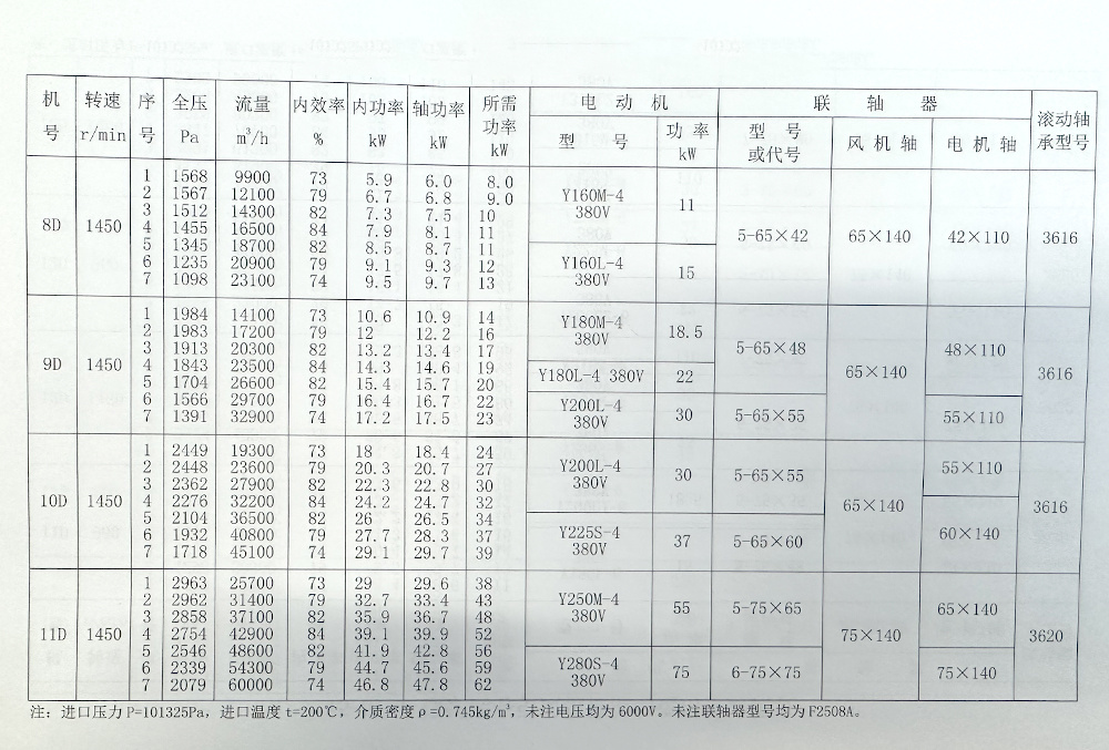
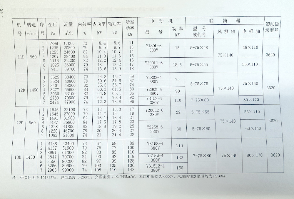
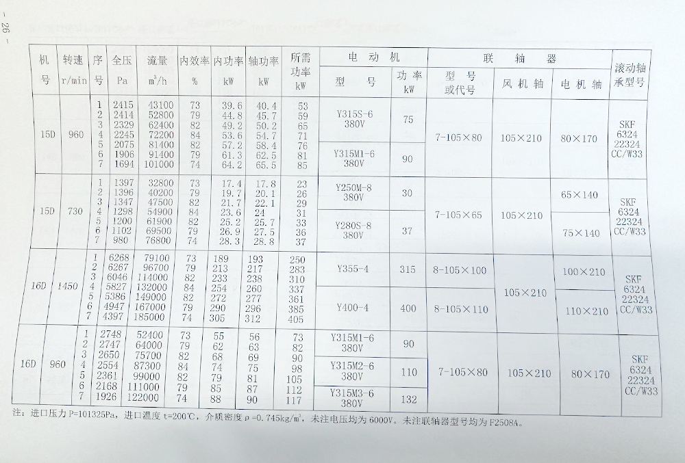
The medium conveyed by the blower is air, while the medium conveyed by the induced draft fan is flue gas or gas containing particulate impurities. It can be used for more than four years when the impurity concentration is less than 200 mg/m³. If the impurity concentration is higher, it can still be used, but the service life will be relatively shortened. The maximum operating temperature for the induced draft fan should not exceed 250°C.
Type
Blowers and induced draft fans are usually made in a single suction type. There are 20 machine numbers from N8D to 29.5D, totaling 40 specifications.
Each type of fan can be made in either left-handed or right-handed configurations. Viewed from the motor end, any impeller that rotates clockwise is referred to as a right-handed fan, indicated by 'right', while the opposite is referred to as a left-handed fan, indicated by 'left'.
The position of the fan's outlet is indicated by the outlet angle of the casing.
The fan's drive mode is of type D, which is a cantilever structure, with the motor connected to the fan using a flexible coupling for direct drive.
The full product name is exemplified as follows: G5-51-11N18D right 45°; Y5-51-11N18D left 45°.
In this, G and Y represent the boiler blower and boiler induced draft fan, respectively. 5 is the pressure coefficient at the highest efficiency point multiplied by 10, 51 is the specific speed, 1 indicates the first design, and №18 indicates that the impeller diameter is 18000m, with 45° being the outlet angle.
Features
1. The design of this series of fans is based on aerodynamic sketches that have been modeled and tested for over a year, utilizing patented technology for 'adjustable air inlets'; high-strength, wear-resistant impellers, oil-sealed bearing boxes, and self-aligning axial adjustment doors are among the advanced proprietary technologies.
2. The efficient operating range is wide, with a dense arrangement of machine numbers, making it easy to select high-efficiency operating points.
3. It features patented technology for 'adjustable air inlets'.
This patented technology allows for adjustment to the ideal position during fan installation.
During fan operation, if there is friction, the air inlet can be adjusted to an appropriate position.
During fan maintenance, the air inlet can be adjusted axially to disengage from the impeller, allowing the rotor to be vertically suspended.
4. High-strength, wear-resistant impeller
The impeller uses near-diameter, backward-curved single blades to reduce airflow impact, ensuring good stability, preventing motor overload, and overcoming issues such as internal dust ingress and vibration caused by non-working area dust after the original 4-73 wing-type hollow blades wear through. The easily worn parts of the induced draft fan blades are welded with special wear-resistant welding rods, significantly extending the fan's service life. This type of fan has a high pressure coefficient, low peripheral speed, and low noise, making it highly practical.
5. Oil-sealed bearing box
It uses a lap-type oil throw ring to throw oil brought up by the high-speed rotating bearings onto the inner wall of the bearing box, returning it to the oil pool; the semi-open aluminum oil seal not only facilitates maintenance and prevents friction accidents but can also increase resistance axially to intercept some thin oil back to the oil pool; the external pressure packing prevents a small amount of thin oil from leaking; the upper part of the bearing box is equipped with a vent plug, reducing the micro-positive pressure inside the bearing box, ensuring no oil leakage and good dust-proof performance.
6. Self-aligning axial adjustment door
The adjustment door's guide blades are equipped with self-aligning bearings, allowing for flexible and effortless adjustment without 'dead' points during operation and adjustment, ensuring that the actuator does not overload and can be used outdoors.
7. This fan is either a whole or split assembly.
For this series of fans, the drive group, motor, and coupling cover for models below N16D are assembled on a complete base before leaving the factory; the casing, air inlet, and adjustment door form another base. Smaller models are assembled into two bases before leaving the factory, while larger models are disassembled into three bases (with the motor being another base).
8. This fan is fully equipped.The adjustment door, coupling cover, inlet and outlet flanges, complete machine foundation bolts, flexible connections for inlet and outlet, and vibration measurement instruments for medium and large models can also be equipped with complete actuators, dampers, and silencers as needed.
10. Comprehensive related parameters provided.
Main component weights, static and dynamic loads, rotor flywheel torque, resistance torque curve during fan startup, resistance torque and dimensions of the adjustment door, etc. Holding the sample of this series of fans allows for construction design.
11. This fan is easy to install and maintain.
This fan has two complete bases, with the casing and drive group. The casing has a mid-split or vertical split, making disassembly particularly convenient; the rotor can be vertically suspended, and if only the impeller is replaced, it can also be disassembled axially.
12. Key quality assurance measures for the product.
(1) Designed and manufactured according to national and industry standards.
(2) Fan performance is derived from similarity calculations based on fan model tests.
(3) For impellers with a diameter greater than 2m or a peripheral speed exceeding 100 m/s, non-destructive testing is conducted according to standards.
(4) For high peripheral speeds, reinforced blades are used, and the easily worn parts of the induced draft fan blades are welded with special wear-resistant welding rods, allowing users to perform self-welding after on-site wear.
(5) Both the inlet and outlet of the fan are equipped with flexible connections to prevent stress interference caused by deformation of the pipeline and fan.
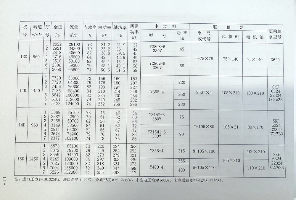
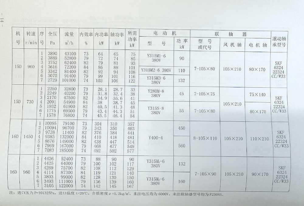
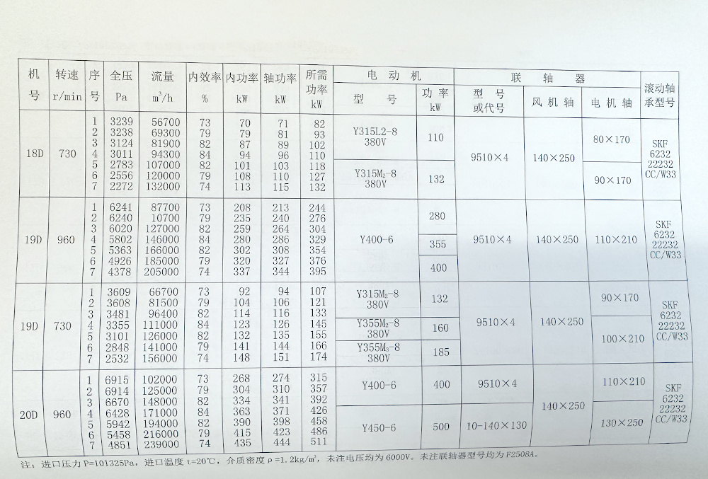
(6) The N14 D to 29.5 D ventilators all use SKF imported rolling bearings.
All units above No. 16 D are equipped with vibration protection devices to prevent damage due to vibration.Installation adjustment and trial operation.
Before installation, first prepare all materials and tools needed for installation, and check each part of the fan. Special attention should be paid to the inspection of components such as the impeller, main shaft, and bearings. If any damage is found, it should be repaired, and then the inside of the bearing box should be cleaned with kerosene.
1. During the installation operation, attention must be paid to:
1. To prevent rust and reduce disassembly difficulties, a small amount of grease or machine oil should be applied to some joint surfaces.
2. When tightening bolts on the upper joint surface, if there are positioning pins, they should be tightened first before tightening the bolts.
3. Check the inside of the casing and other housings to ensure there are no dropped or left tools or debris.2. Installation requirements:
1. Install according to the positions and dimensions shown in the drawings. To achieve high efficiency, special attention should be paid to ensuring the gap size between the air inlet and the impeller. Maintain the axial gap of the rolling bearing outer sleeve and coupling for safe operation.
2. Ensure the levelness of the main shaft, measure the concentricity of the fan main shaft and motor shaft, and the parallelism of the two ends of the coupling. The allowable tolerance for the two shafts' eccentricity is 0.05mm.
3. When installing the adjustment door, be careful not to install it in reverse; the air intake direction should be consistent with the impeller rotation direction.
4. When installing the inlet and outlet pipelines of the fan, the weight should not be applied to the casing.
5. After all installations, conduct a comprehensive inspection. Only after passing the inspection can the operation test be carried out.3. Trial operation of the fan:
The mechanical operation test should first be conducted without load, that is, with the inlet pipeline gate or adjustment door closed. If the operation is good, then conduct continuous operation under full load normal conditions (specified full pressure and flow) for the specified time. If no abnormal phenomena occur, it can be put into production.
For trial operation after repair and installation, the time should not be less than 30 minutes, and for new installations, the trial operation time should not be less than 2 hours.Operation.
1. Operating procedures for the fan:
Before starting the fan, the following preparatory work should be done:
1. Close the adjustment door.
2. Check the gap sizes of each part of the fan and whether there are any scratches or collisions between rotating and fixed parts.
3. No one is allowed to stand near the impeller radius or near the coupling.
4. Check whether the oil level in the bearing box meets the standard.
5. Check whether the electrical wiring and instruments are correct.
6. Check whether the cooling parts are normal.
After the fan starts and reaches the normal speed, gradually open the adjustment door until the specified load is reached.
During operation, the temperature rise of the bearings should not exceed 40°C, and the surface temperature should not exceed 80°C. If the temperature rise is too high, water cooling can be used, generally considering 0.5~1m/h. If the effect is not good, the water flow can be appropriately increased.2. Emergency stop of the fan:
In the following situations, an emergency stop must be performed:
1. The fan has severe noise.
2. The bearing temperature rises sharply.
3. The fan vibrates violently or there are impact sounds.Maintenance.
1. The fan must not operate with 'illness'.
2. Debugging and repairing the fan must be done with the power off.
3. Regularly remove dust, dirt, and water impurities from the inside of the fan, and prevent rust.
4. The sensitivity of the thermometer and oil gauge should be checked regularly.
5. Apart from replacing the lubricating oil after each disassembly and repair, under normal circumstances, the lubricating oil should be replaced every 3 to 6 months.G5-51-1 Boiler Centrifugal Blower Performance and Selection Parts Comparison Table.


FAQ
Can I have my own custom product?
Yes. oem and odm can be provided, including design, logo, packaging, etc.
What is the minimum order quantity?
It depends on the product.
What are the terms of payment?
Wire transfer or letter of credit, Western Union, Alipay, etc.
When is the delivery time?
Inventory orders within 7-15 days, for oem and odm orders, the specific time depends on the actual situation.
Can I take samples for testing?
Yes, samples can be sent for testing before bulk ordering.
Do you have pre-shipment inspection procedures?
Yes, we always test the products before delivery.
Inquiry Message
Note: Please leave your contact information and our professionals will contact you as soon as possible!
Related Products


