Hebei Zhengtian Fan Manufacturing Co., Ltd.


Contact Us
E-mail:
youtian@hbztfj.com
WhatsApp:
Add:
Renqiu City, Cangzhou City, Hebei province, discuss Bao township Shoulian village east Yi road east

Y5-47 type boiler centrifugal induced draft fan
keyword:


- Description
-
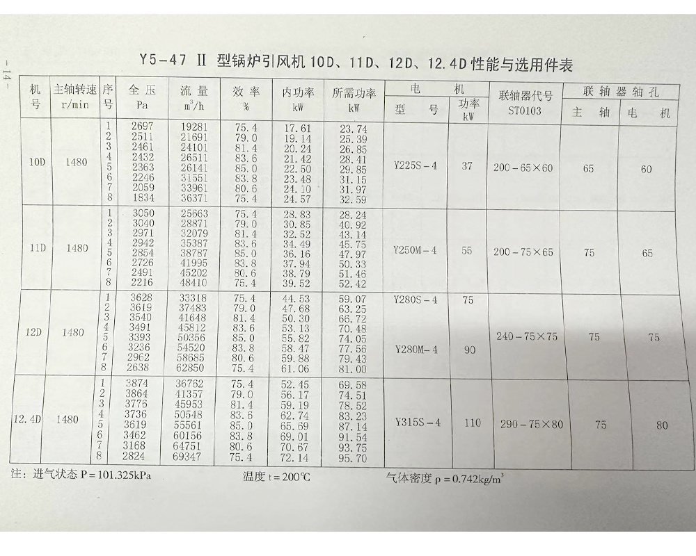
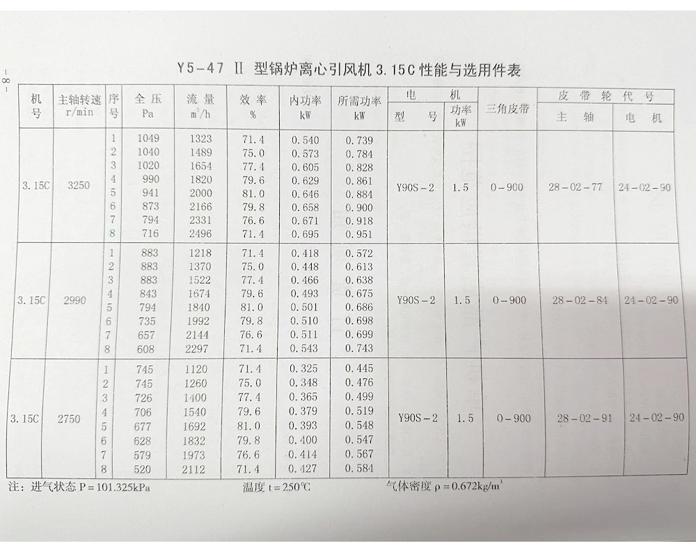
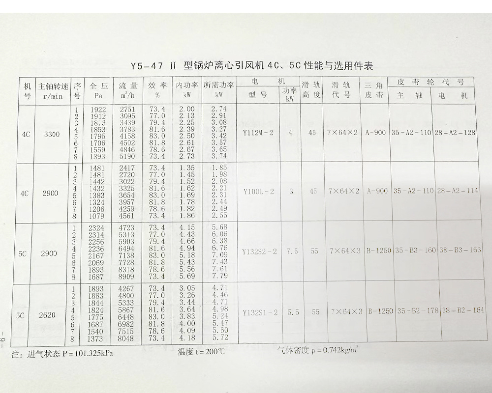
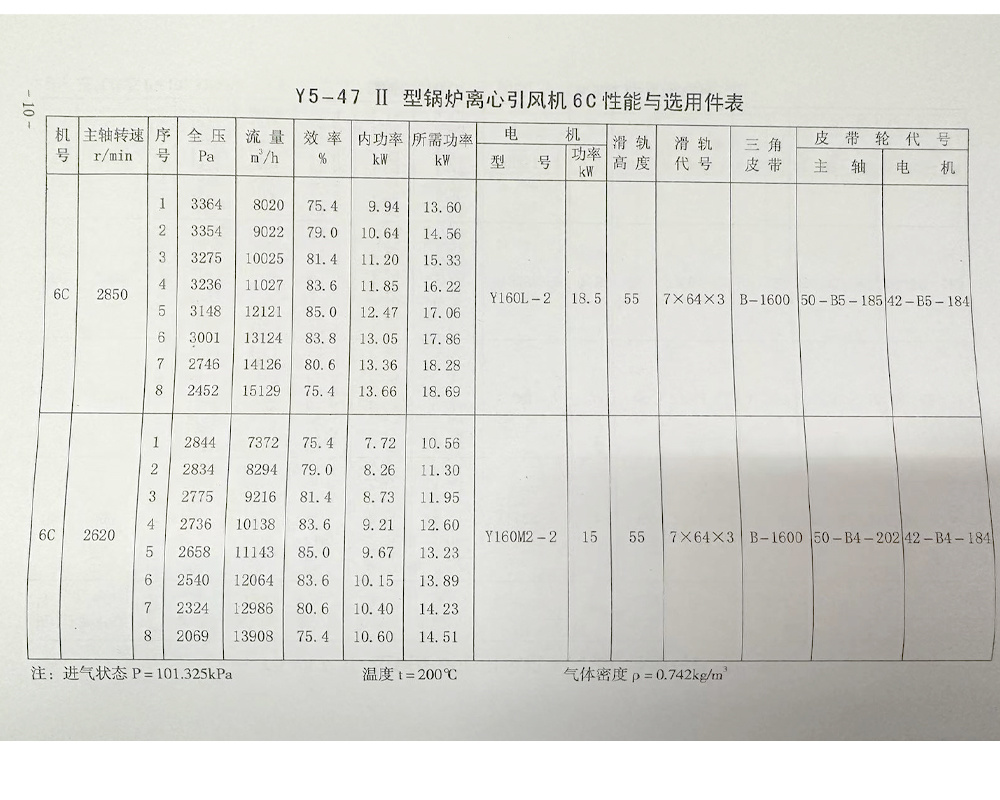
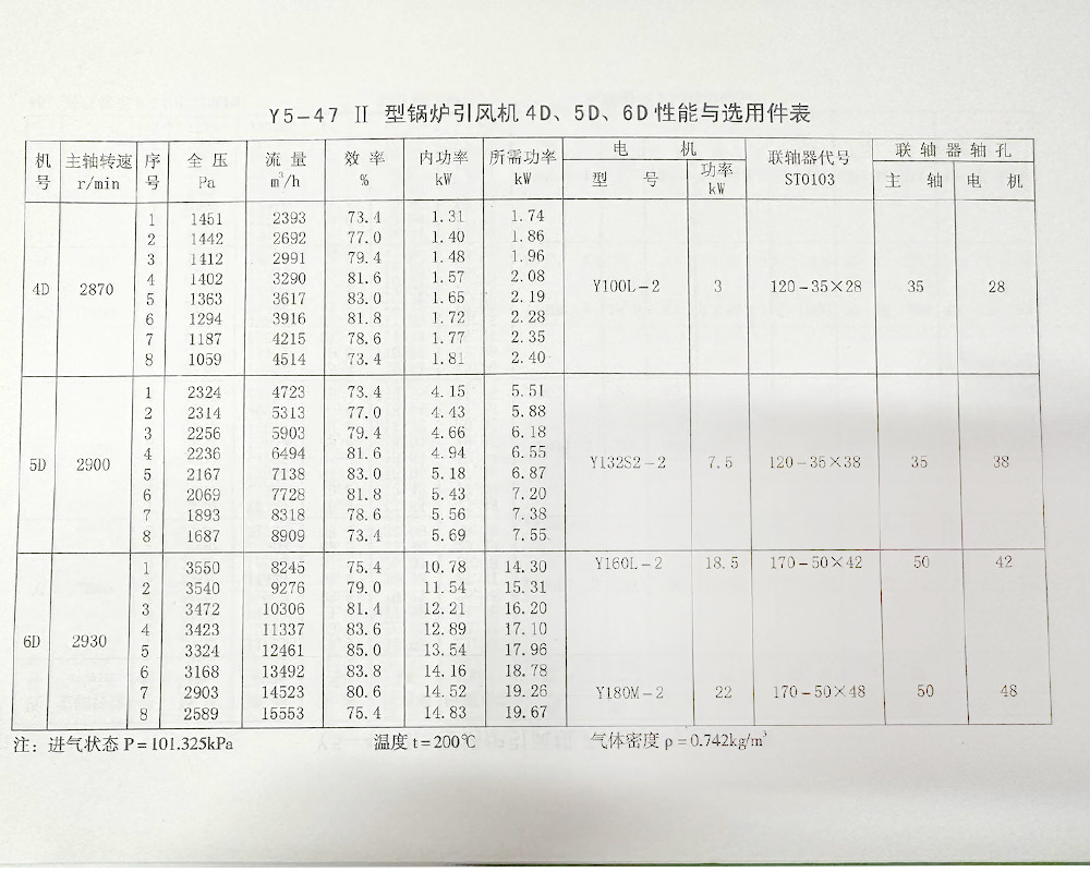
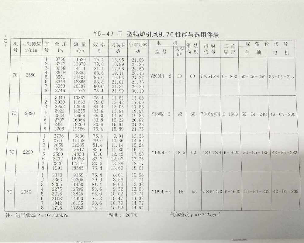
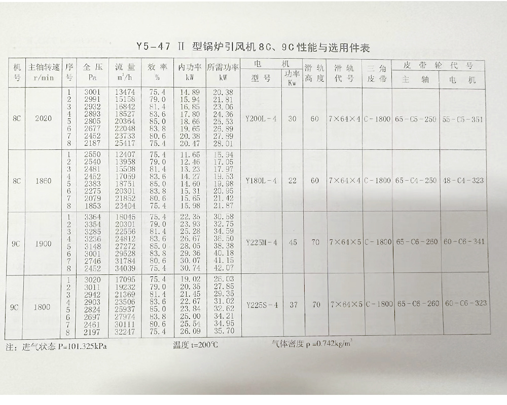
Central air conditioning is certainly convenient, but astronomical quotes force us to choose the Y5-47 type boiler centrifugal induced draft fan in certain situations. The Y5-47Ⅱ type fan has undergone a series of improvements compared to the original Y5-47 type fan, resulting in a significant reduction in noise. Additionally, to better meet the boiler matching requirements, the following seven models have been newly added: M3.15C (for 0.2t/h~0.5t/h), 4D (for 0.7t/h~1t/h), 5D (for 2t/h), 6D (for 4t/h), 7C (for 4t/h, 6t/h), 10D (for 6t/h), 11D (for 10t/h).
Applications and Features
The Y5-47Ⅱ type boiler centrifugal induced draft fan is suitable for industrial boilers burning various coal qualities and equipped with smoke and dust removal devices ranging from 0.2t/h to 20t/h. It can be used as long as the intake conditions are comparable and the performance is compatible, but the higher temperature should not exceed 250℃. Currently, there are many series models of industrial boilers, with varying coal qualities and different resistance from matching dust collectors and pipelines, resulting in significant differences in the required fan air volume and pressure. To adapt to these situations, this fan adopts two transmission methods: D type and C type (i.e., coupling and V-belt drive). Among them, the D type induced draft fan matches with boilers from 0.7t/h to 20t/h, while the C type induced draft fan matches with boilers from 0.2t/h to 10t/h. For units using V-belt drive, the main shaft speed can be adjusted according to actual conditions to achieve the desired air volume and pressure.
Types
1. The induced draft fan is made with a single suction design, with models including №3.15, 4, 5, 6, 7, 8, 9, 10, 11, 12, and 12.4, totaling eleven types.
2. The induced draft fan can be made in both left-handed and right-handed types. When viewed from the drive group end, if the impeller rotates clockwise, it is called right-handed, denoted as "right"; conversely, it is called left-handed, denoted as "left".
3. The position of the fan outlet is indicated by the angle of the casing outlet. Both "left" and "right" can be made at angles of 0°, 90°, and 180°.
4. The fan's transmission methods are C type and D type, with the motor connected to the fan using belt drive and elastic coupling direct drive, respectively.
5. If the above transmission methods, outlet angles, and model numbers cannot meet your production needs, our factory is capable of designing and modifying according to the on-site conditions.Structure and Characteristics
The fan consists of parts including the impeller, casing, inlet, drive group, and regulating door.
1. The impeller is made of 12 pieces of 16Mn backward-inclined flat blades welded between the arc conical cover and flat disc. It has been dynamically balanced and tested for overspeed operation, ensuring stable and reliable operation. Its strength, durability, and service life are among the best in various types of fans.
2. The casing is a spiral shell made of welded steel plates. It is universal for left and right rotation above N8.
3. The drive group - the main shaft is made of high-quality steel, using two parallel bearing seats with ball bearings (N3.15~7 uses low-noise bearings), lubricated with No. 2 calcium-sodium grease, with self-cooling blades and a simple structure.
4. The inlet - the converging inlet is made as an integral structure, fixed with screws on the fan's inlet side.
5. The regulating door - all Y5-47 series fans are equipped with regulating doors to adjust the fan's flow. Fans below N6 use three blades with a louver structure, which is flexible to close and has a simple structure; fans above N7 use a petal-type centering regulating door, which has high adjustment efficiency and reliable structure. The regulating door is axially installed before the inlet, with an adjustment range from 90° (fully closed) to 0° (fully open). The position of the regulating door handle, when viewed from the inlet direction, for right-handed fans, turning the handle counterclockwise goes from fully closed to fully open; for left-handed fans, it is the opposite.
To ensure the normal operation of the regulating door, proper lubrication must be maintained. Due to the high temperature of the induced draft fan, high-temperature (260℃) grease is used to ensure it does not fail during high-temperature operation.
Installation Adjustment and Trial Operation
1. Before installation, a comprehensive inspection of all fan components should be conducted: check if the parts are complete, whether the rotation direction of the impeller and casing is consistent, if all connections are tight, and if there is any damage to the impeller, main shaft, bearings, etc. The drive group should be flexible and effective. If any issues are found, they should be repaired.
2. During installation: pay attention to check the casing; there should be no dropped or left tools and debris inside the casing. To prevent rust and reduce disassembly difficulty, some grease or machine oil should be applied to some joint surfaces. The connection surfaces between the fan and the foundation, as well as the inlet and outlet connections with the pipeline, should be adjusted to fit naturally without forcing connections, and no weight should be placed on the fan. Ensure the fan is level. Both bearings must be cleaned and re-lubricated (with No. 2 calcium-sodium grease).
3. Installation Requirements:
① Install according to the position and dimensions shown in the drawings. To ensure the fan's flow and pressure, the axial and radial clearances between the inlet and the impeller must be guaranteed. In the installation diagram, the motor slide rail foundation and bracket should be on the same horizontal plane.
② When installing № 4~12.4D type fans, ensure the horizontal position of the fan's main shaft and the coaxiality of the motor shaft. The coupling installation must meet the technical requirements for elastic coupling installation. For C type drive fans, the grooves of the main shaft V-belt and the motor V-belt pulley must not be misaligned. After putting on the tape, a safety cover (user-made) should be installed for safety.
③ When installing the regulating door, be careful not to install it in reverse, ensuring the air intake direction is consistent with the impeller rotation direction.
④ After installation, test the drive group to check for any tightness or scraping issues. The power required by the fan is calculated based on: intake temperature of 250℃ (N3.15C), 200℃ (N4~12.4). During trial operation, if the intake temperature is significantly lower than the above temperatures, the flue gas density will increase. If the regulating door is fully open during operation, there will inevitably be excessive current, which may burn out the motor. To avoid this, the regulating door should be closed during startup, and after starting, the regulating door should be gradually opened while strictly controlling the current within the rated value.
The newly installed fan must run for no less than 2 hours during trial operation, and the fan that has been repaired must run for no less than half an hour. After installation, the fan must not have any abnormal phenomena such as unusual vibration, odor, noise, or leakage of electricity and gas before it can be officially used (during trial operation, the bearing...
During the furnace ignition process, the flue gas temperature gradually rises until it stabilizes at the normal operating temperature (around 180~250℃). The temperature rise must not exceed 40℃. To prevent burning out the motor, the adjustment door must be gradually opened during the ignition process, strictly controlling the current within the rated value. When the flue gas temperature reaches around 200~250℃ during normal boiler operation, the adjustment door can be fully opened.
If the flue gas temperature through the fan is still below 200~250℃ (or much lower) during normal boiler operation, causing the motor current to exceed the rated value, the motor power should be recalculated and a larger power motor should be selected according to this manual.
Maintenance of the fan
1. Regularly clean the inside of the fan according to usage, especially the dust and dirt on the blades, and prevent rust.
2. Periodically check the lubricating grease in the bearings. If it is found to be deteriorated, it must be replaced in a timely manner. In addition to replacing the lubricating grease during machine repair, it should be removed about once a month, and the bearing side cover and the countersunk screws on the bearing seat should be removed to inject No. 2 calcium-sodium-based grease (suitable for temperatures below 100℃). The bearings should be cleaned once every six months.
3. Regularly check whether the bearing temperature is normal during operation; the bearing temperature should be less than 100℃.
4. If any abnormal conditions are found during the fan startup, shutdown, or operation, immediate maintenance should be performed.
5. Maintenance of the fan must be carried out when it is stopped, powered off, and under supervision, and it is strictly prohibited for unrelated personnel, children, and those with limited mobility to be present.
6. During the fan trial run and operation, no one is allowed to stand near the air inlet and outlet directions or near the coupling.
Noise of the fan
This series of fans is one of the lower noise fans among the existing industrial boiler induced draft fans in the country. When the fan leaves the factory, its noise index meets the noise limit values for ventilators issued by the Ministry of Machinery Industry (JB/TQn314-84). However, sometimes the fan may produce louder noise during operation, mainly due to the following reasons:
1. Due to improper selection, the actual operating point of the fan is far from the point of highest efficiency (beyond the 8 performance points in the performance table).
2. Due to severe fan vibration.
3. The shaft and rolling bearings are installed misaligned, with the front and rear bearings being eccentric.
4. The pulley or coupling is installed misaligned.
5. Bearing wear or poor quality, unclean, or deteriorated lubricating grease.
6. Fans below No. 7 do not use low-noise bearings (307Z, 309Z, 312Z).
Inquiry Message
Note: Please leave your contact information and our professionals will contact you as soon as possible!
Related Products


